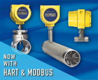
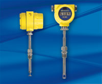
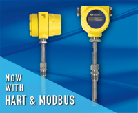
The ST75 Series thermal flow meters are a compact, low cost solution for accurate, repeatable direct mass flow measurement of air and gases. These in-line (spool-piece) style flow meters have no moving parts and are available for use in pipe diameters from 1/4 inches to 2 inches, [6 mm to 51 mm]. Process connection options include male NPT, female NPT, and flanged. These thermal flow meters feature wide 100:1 turndown and depending on pipe size, will measure from 0.01 SCFM to 559 SCFM [0,01 NCMH to 950 NCMH].
The ST75 Series electronics are housed in rugged, IP67 rated enclosure with dual conduit ports in either NPT or M20 threading. The instrument comes standard with dual 4-20 mA outputs and a 500 Hz pulse output. The models ST75A and ST75AV include HART or Modbus, as well as NAMUR compliant 4-20 mA outputs and SIL compliance rating. The flow meter’s transmitter/electronics can be integrally mounted with the flow element (probe) or be remote mounted to best match your installation situation. The complete instrument carries global Ex agency approvals for Division l/Zone 1 installations.
The ST75 flow meter sensing element features precision, platinum RTD in small diameter, “equal-mass,” all-metal thermowells to provide superior accuracy, repeatability and fast response. The “V” suffix models (ST75V and ST75AV) include Vortab® flow conditioners built-in to the spool-piece to provide accurate and repeatable flow measurement installations with limited straight-run and/or for operating in transitional flow ranges.
- Brand
- APPLICATIONS
- SPECIFICATIONS
- CERTIFICATION/APPROVALS
APPLICATIONS
- Burner and boiler fuel and air feed lines
- Industrial furnaces, kilns and oven fuel/air controls
- Natural gas sub-metering
- Chiller air flow measurements
- Dosing and gas injection rate controls
- Heat treating gas controls industrial furnaces, kilns and oven fuel/air controls
- Air compressor system control and point-of-use monitoring
- Co-gen and turbine generator fuel flow measurements
SPECIFICATIONS
Warranty:
ST75, ST75V: 1 year
ST75A, ST75AV: 2 years
Media Compatibility: Air, compressed air, nitrogen, oxygen, argon, CO2, ozone, other inert gases, natural gas, and other hydrocarbon gases.
Pipe/Line Size Compatibility: 1/4″ to 2″ [ 6 mm to 51 mm]
| ST75 | ST75A | ST75V | ST75AV | |
| Vortab flow conditioning | ■ | ■ | ||
| Dual 4-20 mA outputs | ■ | ■ | ■ | ■ |
| 4-20 mA per NAMUR NE43 | ■ | ■ | ■ | ■ |
| HART or Modbus I/O | ■ | ■ | ||
| 500 Hz pulse output | ■ | ■ | ■ | ■ |
| Maximum remote distance | 50′ [15 m] | 100′ [30 m] | 50′ [15 m] | 100′ [30 m] |
| SIL compliance rating | ■ | ■ | ||
| Warranty Standard | 1 year | 2 years | 1 year | 2 years |
Range:*
| NPT Line Size | 1/4″ | 1/2″ | 3/4″ | 1″ | 1 1/2″ | 2″ |
| Min. SCFM | 0.04 | 0.13 | 0.22 | 0.35 | 0.85 | 1.40 |
| Min. [NCMH] | [0,07] | [0,22] | [0,38] | [0,59] | [1,44] | [2,38] |
| Max. SCFM | 17.34 | 50.64 | 88.88 | 139.95 | 339.31 | 559.27 |
| Max. [NCMH] | [29,47] | [86,04] | [151,00] | [237,78] | [576,48] | [950,20] |
| Tubing Line Size | 1/4″ | 1/2″ | 1″ |
| Min. SCFM | 0.01 | 0.05 | 0.25 |
| Min. [NCMH] | [0,01] | [0,09] | [0,42] |
| Max. SCFM | 3.02 | 21.15 | 99.08 |
| Max. [NCMH] | [5,14] | [35,94] | [168,33] |
* Actual range subject to gas type and specific conditions.
- Accuracy:
Model ST75, ST75 A
Standard: ± 2% reading, ± 0.5% full scale
Optional: ± 1% reading, ± 0.5% full scale
Model ST75V, ST75AV
Standard: ± 1% reading, ± 0.5% full scale
- Temperature Coefficient: (at calibrated conditions)
With optional extended temperature compensation; valid from 10% to 100% of full-scale calibration
Flow: Maximum ± 0.025% of reading/ºF up to 250ºF [±0.05% of reading/ºC up to 121 ºC]
Repeatability: ± 0.5% reading
Turndown Ratio: Factory set at 3:1 to 100:1
Temperature Compensation:
- Standard 40°F to 100°F [4°C to 38°C]
- Optional: 0°F to 250°F [-18°C to 121°C]
Turndown Ratio: 10:1 to 100:1
- Agency Approvals:
| FM, FMc: | Class I, Division 1, Groups B, C, D; T4 Ta= +60°C; Type 4X, IP66 Class II/III, Division 1, Groups E, F, G; T4 Ta= +60°C; Type 4X, IP66 Model ST75 and ST75V also include: Nonincendive for Class I, Division 2, Groups A, B, C and D; T4 Ta= + 60°C; Type 4X, IP66 |
| ATEX: | Zone 1, Zone 21 II 2 G Ex db IIC T6…T1 Gb II 2 D Ex tb IIIC T85°C…T300°C Db; IP66/IP67 Ta= – 40°C to + 65°C |
| IECEx: | Ex db IIC T6…T1 Gb; Ex tb IIIC T85°C…T300°C Db; IP66/IP67 Ta= -40°C to +65°C |
| Other: | EAC/TR CU (Russia), Kazakh MPA, NEPSI, CE Marking, CPA, PED, EAC/TR CU pressure directive 032-2013, CRN |
| SIL (ST75A, ST75AV): | SIL 1 compliant, safe failure fraction (SFF) 78.5% to 81.1% |
Flow Element
Installation: In-line “T”, NPT or tube
Type: Thermal dispersion
Materials of Construction: All-welded 316 stainless steel probe element with Hastelloy-C22 thermowells; 316 stainless steel NPT and tube fittings; ST75 V and ST75 AV flow body is schedule 40 stainless steel.
Process Connection:
- T-fitting [NPT female]: 1/4″, 1/2″, 3/4″, 1″, 1 1/2″ or 2″
- Tubing: 1/4″, 1/2″ or 1″
Operating Temperature: 0°F to250°F [-18°C to 121°C]
Operating Pressure:
- T-fitting [NPT female]: 240 psig [16,5 bar(g)]
- Tube: 600 psig [ 41 bar(g)]
Flow Transmitter
- Enclosure:
Rating: NEMA 4X, IP66, IP67
Material:
Standard– polyester powdered coated, ≤0.4% CU, low/no copper content*2 aluminum
(*2: Standard effective April 2023)
Optional– 316 stainless steel
Conduit/Cable Port: Dual 1/2″ NPT or M20x1.5
Input Power:
DC: 18 Vdc to 36 Vdc
AC: 85 Vac to 265 Vac (*CE Marking approval from 100 Vac to 240 Vac
- Operating Temperature Range: 0°F to 140°F [-18°C to 60°C]
- Output Signal
Standard
(2) 4-20 mA, user assignable to flow rate and/or temperature
(1) 0-500 Hz pulse for total flow
Output #1 have fault indication per NAMUR NE43 guidelines; user selectable for high (> 21.0 mA) or low (< 3.6 mA
- Bus Communications (Models ST75A and ST75AV only)
HART: Version 7. FieldComm Group certified. Available over output #1; DD file included.
Modbus: RS485 (RTU and ASCII). Standard MS (16 bit), Standard LS (16 bit), and Daniel extension (32 bit).
- Communication Port: RS232C standard
- Digital Display (optional): 2-line x 16 characters LCD. Displays measured value and engineering units. Top line assigned to flow rate. Second line is user assignable to temperature reading, as flow totalizer or alternating. Display can be rotated in 90° increments for optimum viewing orientation.


