

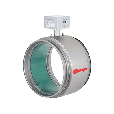


Velocity measurement in full cross-section version. Continuous velocity measurement in tube version for careful material transport. Measures in full cross-section

- Brand
- FEATURES & BENEFITS
- MAIN APPLICATIONS
- TECHNICAL SPECIFICATIONS
- TECHNICAL DATA
- MOUNTING & INSTALLATION
Brand
Envea SWR
FEATURES & BENEFITS
- Continuous speed measurement of solids (powder, granules, dust ) in metal pipes
- Measurement directly in the conveying stream / entrained flow
- Measurement is completely independent of material
- Sensor is made accordingly to the existing pipe diameter
- Measurement without product contact
MAIN APPLICATIONS
- Plastic industry
- Tobacco
- Food
TECHNICAL SPECIFICATIONS
| TECHNICAL SPECIFICATIONS | |
|---|---|
| Material to measure | Dust, powders or granulates |
| Working principle | Correlation |
| Process pressure | Max. 100 mbar |
| Process temperature | Max. +45°C |
| Mounting | Flare connection |
| Type of Conveying | Pneumatic leanphase |
| Velocity range | 1…35m/s |
| Pipe diameter | Max. 350mm |
| ATEX rating | None |
| Output | 4…20mA, Modbus, Profibus |
TECHNICAL DATA
- Materials: Granules, Powder and dust
- No calibration (Plug & Play)
- Without build-in components into the flow
- Range of application: starts with material speed as low as 0.75 m/s
| SENSOR TECHNICAL DATA | |
|---|---|
| Innerdiameter | DN: 80, 100, 150, 200, 250, 350 (other sizes on request) |
| Material inner pipe | PMMA |
| Mechanical connection | Flare connection |
| Protection category | IP 54 |
| Max. pressure | 100 mbar |
| Velocity range | 1…35 m/s/td> |
| Temperature inside the pipe | 0…+50 °C |
| Temperatur outside the pipe | 0…+45 °C |
| Power supply | 24 V DC |
| Weight | Depend on diameter |
| Measuring accuracy | ± 1 % (in the calibrated measuring range) |
| TRANSMITTER TECHNICAL DATA | ||||
|---|---|---|---|---|
| Transmitter (DIN Rail) | Transmitter (field housing) | |||
| Power supply | 24 V DC ±10 % | 110 / 230 V AC 50 Hz (optional 24 V DC) | ||
| Power consumption | 20 W / 24 VA | |||
| Protection type | IP 40 to EN 60 529 | IP 65 to EN 60 529/10.91 | ||
| Ambient operating temperature | -10 … +45 °C | |||
| Dimensions (W x H x D) | 23 x 90 x 118 mm | 258 x 237 x 174 mm | ||
| Weight | Approx. 172 g | Approx. 2.5 kg | ||
| Connection terminals cable cross-section | 0.2-2.5 mm2 [AWG 24-14] | |||
| Current output | 1 x 4 … 20 mA (0 … 20 mA), load < 500 Ω | 3 x 4 … 20 mA (0 … 20 mA), load < 500 Ω | ||
| Interface | RS 485 (ModBus RTU) / USB | |||
| Pulse output | Open collector – max. 30 V, 20 mA | |||
| Relay contact | Max. rated load: 250 V AC Max. peak current: 6 A Max. rated load 230 V AC: 250 VA Max. breaking capacity DC1: 3/110/220 V: 3/0.35/0.2 A Min. switching load: 500 mW (10 V / 5 mA) | |||
| Data backup | Flash memory | |||
MOUNTING & INSTALLATION
For the assembly of the sensor, the installation location is specified in accordance with the conveyed inlet and outlet paths. At the specified installation location the sensor is installed in the extisting pipeline via a standard flare connection. The distance between sensor and analysis unit can be a maximum of 300 m.
Related Products


More From Avensys
More Services
Our certified engineers and technicians can intervene from the initial consultation and planning stages, throughout the life of instruments and systems.

Field & In House
Develop customized monitoring plans that address client's unique needs...
Start up
Start up & Commissioning is a critical phase in the life cycle of any project.
Integrated Systems
The benefits include improved performance, reduced costs, and increased reliability.
Training
We believe that product training is essential for both our employees and our clients.