

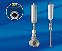
The FS10i is a compact, economical solution to air and compressed air flow metering. It is the first, and currently only, thermal mass flow meter to meet SIL 2. Utilizing application proven thermal mass flow technology, the FS10i provides a highly accurate and repeatable linearized 4-20 mA output of flow rate. Additionally, for applications benefiting from a high or low flow alarm point, the FS10i includes a user programmable 1A SPDT relay output.
- Brand
- FEATURES
- MAIN APPLICATIONS
- SPECIFICATIONS
- APPROVAL & CERTIFICATIONS
Brand
Fluid Components FCI
FEATURES
- Direct Mass Flow Measurement
- Ultra Reliable, No Moving Parts Design
- User-Programmable 4-20 mA Output and Relay Trip Point
- Set-Up Via PC Interface
- 10 LED Display Array
- Easy M12 or Cable Gland Connection WIth Electronics
- SIL 2 Compliance Rating
- Optional Div 2 / Zone 2 Approvals
MAIN APPLICATIONS
- Paint booth ventilation
- Compressed air leak detection
- Packaging and wrapping machinery air flow
- Clean room air flow
- Burner, furnace and boiler intake air
SPECIFICATIONS
Instrument
- Measuring Principal: Thermal dispersion
- Fluid Type: Air, compressed air
- Range
In-line
Air
1 ″: 1 SCFM to 50 SCFM [1,6 NCMH to 80 NCMH]
2 ″: 2 SCFM to 200 SCFM [3,2 NCMH to 320 NCMH]
Compressed Air
1 ″: 1.5 SCFM to 150 SCFM [2,4 NCMH to 240 NCMH]
2 ″: 4 SCFM to 400 SCFM [6,4 NCMH to 640 NCMH]
Insertion
Air: 1.25 SFPS to 125 SFPS [0,4 NMPS to 38 NMPS]
Compressed Air: 4 SFPS to 400 SFPS [1,2 NMPS to 122 NMPS]
- Accuracy: ± 1.5 % rdg, ± 0.5 % FS
- Pressure Service:
Air: 10 to 50 psi(s) [0,7 to 3,5 bar(a)]
Compressed Air: 50 to 165 psi(s) [3,5 to 11,4 bar(a)]
optional 2 inch inline, 2 to 200 SCFM version: 10 to 50 psi(s) [0,7 to 3,5 bar(a)]
- Temperature Compensation
| Air | Compressed Air | |||
| In-line | Insertion | In-line | Insertion | |
| Standard | 30 °F to 180°F [-1°C to 82 °C] | 40 °F to 100°F [4 °C to 38 °C] | 30 °F to 180°F [-1 °C to 82 °C] | 40 °F to 120°F [4 °C to 49 °C] |
| Optional | 30 °F to 180°F [-1 °C to 82 °C] | 30 °F to 180°F [-1 °C to 82 °C | ||
- Process Connections
In-line: 1 ″ or 2 ″ pipe tee, FNPT threads
Insertion: 1/2 ″ MNPT compression fitting with either Teflon or metal ferrule
- Repeatability: ± 0.5 % of reading
- Response Time: 4 sec. (1 time constant)
- Temperature Coefficient For temperatures > ± 30 °F [± 16 °C]
Maximum ± 0.025 % of reading / °F up to 250 °F [± 0,05 % of reading / °C up to 121 °C]
Flow Element
- Materials of Construction (Wetted Parts)
In-line: 316 stainless steel pipe tee; 316L stainless steel flow element with Hastelloy C-22 thermowells
Insertion: 316L stainless steel with Hastelloy-C22 thermowells
- Operating Temperature
-40 °F to 250 °F [-40 °C to 121 °C]
Teflon ferrule maximum temperature is 200 °F [93 °C]
- Operating Pressure
In-line: 225 psi [15.5 bar]
Insertion: 500 psi [34 bar]
Teflon ferrule maximum pressure is 150 psig [10 bar(g)]
- Insertion “U” lengths
6 ″ [152 mm] with variable insertion depth, 1/2 ″ MNPT compression fitting with Teflon or metal ferrule
12 ″ [305 mm] with variable insertion depth, 1/2 ″ MNPT compression fitting with Teflon or metal ferrule
Electronics
- Display
10 segment LED array, sequential lighting related to flow rate and flashing when trip point exceeded
- Output Signals
Analog: 4-20 mA *
Relay: SPDT, 1A @ 24 Vdc, 120 Vac (ATEX: DC only)
Serial: RS232C I/O
* 500 ohm maximum load; user scalable, general purpose; fault indication per NAMUR NE43 guidelines, user-selectable for high (> 21.0 mA) or low (< 3.6 mA) default
- Instrument Set-up
Free FCI set-up and configuration software utility program and 3-wire-to-DB9 RS232 dongle are supplied for interface of the FS10i to user’s PC. This interface is required to set the 4-20 mA output for the specific line size, flow range, and engineering units, as well as alarm trip point, hysteresis, and trip time delay.
- Trip Point Hysteresis Control: 0-100% of span
- Trip Point Time Delay: user settable for 0-65,000 seconds
- Input Power: 24 Vdc (21.5 Vdc to 30 Vdc); 2.5 watts maximum
- Operating Temperature: -40 °F to 160 °F [-40 °C to 71 °C]
Enclosure / Housing
- Material: stainless steel body; aluminum end-cap/top with polyester overlay and clear, silicone sheath impact guard
- Protection Ratings
Non-Ex installations: IP65, IP66, IP67
FM, FMc approved: NEMA 4X
ATEX, IECEx approved: IP64
- Agency Approvals
FM , FMc Nonincendive, Class I Division 2 Groups A, B, C, D;
Class II, Division 2 Groups E, F, G; Class III,
T4@Ta=71°C, Type 4X
ATEX , IECEx Nonincendive for gas and dust, Zone 2
II 3 G Ex ec IIC T4 Gc, -40°C ≤ Ta ≤ +71°C
II 3 D Ex tc IIIC T81 °C Dc, -40°C ≤ Ta ≤ +71°C
IP64
Others: EAC/TR CU
Ingress Protection IP65, IP66, IP67 in non-hazardous locations
CE Marking, CRN, complies with Canadian Electrical code requirements of ANSI / ISA 12.27.01-2011 as a single seal device
- IEC 61508 (SIL): SIL 2 Compliant; Safe Failure Fraction (SFF) 90%
- Warranty: 1 Year
APPROVAL & CERTIFICATIONS
![]()
![]()
![]()
![]()
![]()
![]()
- FM , FMc Nonincendive, Class I Division 2 Groups A, B, C, D;
Class II, Division 2 Groups E, F, G; Class III,
T4@Ta=71°C, Type 4X
- ATEX , IECEx Nonincendive for gas and dust, Zone 2
II 3 G Ex ec IIC T4 Gc, -40°C ≤ Ta ≤ +71°C
II 3 D Ex tc IIIC T81 °C Dc, -40°C ≤ Ta ≤ +71°C, IP64
- EAC/TR CU
- Ingress Protection: IP65, IP66, IP67 in non-hazardous locations
- CE Marking, CRN, complies with Canadian Electrical code requirements of ANSI / ISA 12.27.01-2011 as a single seal device
- IEC 61508 (SIL): SIL 2 Compliant; Safe Failure Fraction (SFF) 90%


More Services

Field & In House
Start up
Integrated Systems