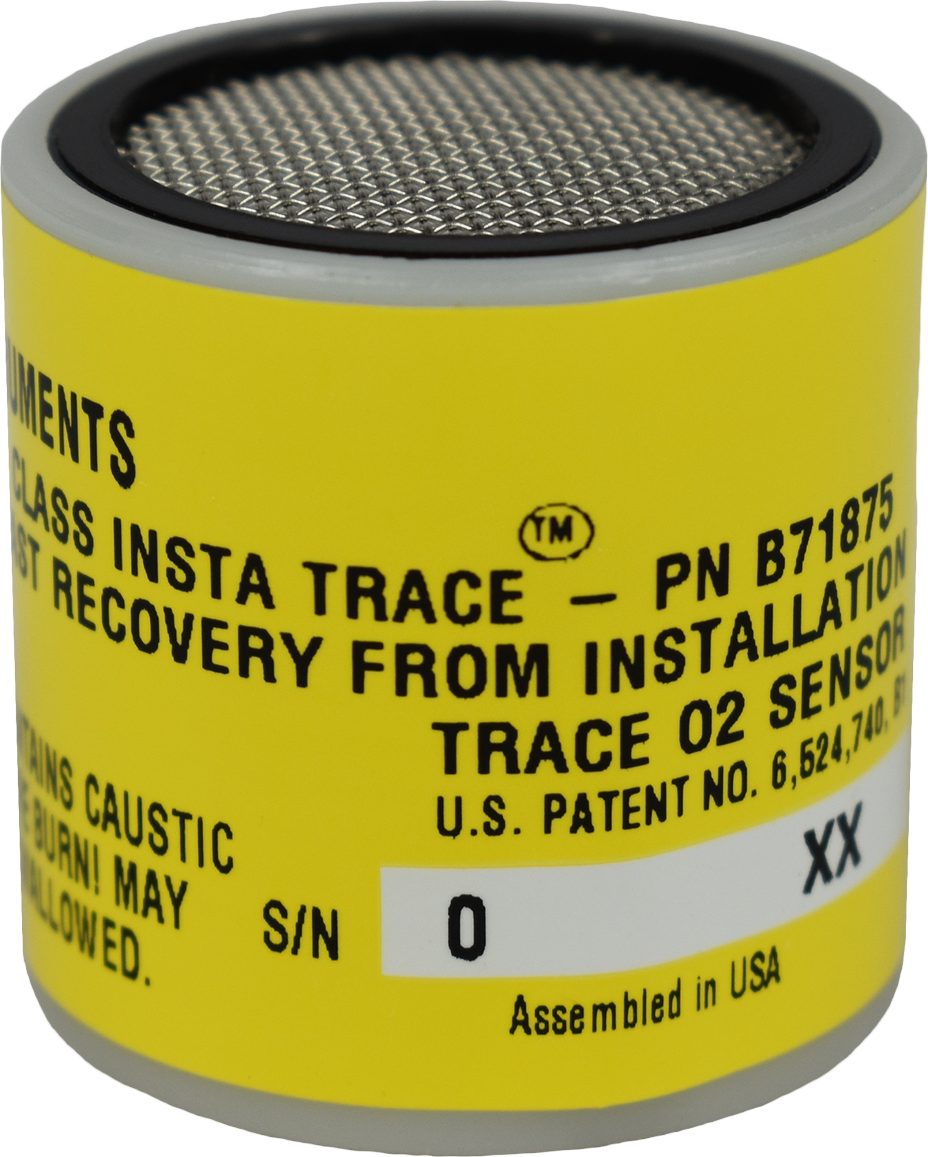
Teledyne’s patent pending innovation called InstaTrace eliminates the greatest inconvenience associated with electrochemical oxygen sensors at the trace level — the wait.When a typical electrochemical trace oxygen sensor is removed from its barrier bag for the purpose of replacing an expired sensor, it is exposed to ambient air (209,000 ppm O2).
During this transition from an oxygen free environment to open exposure, the sensor’s electrolyte becomes saturated with dissolved oxygen — and the longer the exposure, the longer the recovery time. The typical recovery period when replacing a sensor is between 6 to 24 hours.The InstaTrace Micro-fuel Cell oxygen sensor is capable of measuring below 1 ppm of oxygen within 15 minutes of installation. By reducing the recovery period from several hours to just minutes, users will no longer have to divert unanalyzed product, go to liquid back-up (in the case of the air separation industry), or switch analyzers. The intrinsic value of this innovation has extreme significance in plant operation.
- OVERVIEW
- INSTALLATION
OVERVIEW
Teledyne can retrofit InstaTrace sensing capability into all of its Micro-fuel Cell based trace oxygen analyzers currently in service. The retrofit kit contains the cell holder in addition to the InstaTrace sensor. Simply replace the old cell holder (the bottom piece that either threads or mechanically clamps to the cell block assembly) and install the InstaTrace sensor. Take advantage of this innovation by ordering the appropriate retrofit kit.
| ANALYZER MODEL | RETROFIT KIT PART NUMBER |
| 3000T Series | C-71792-A |
| 316 Series | C-71792-B |
| 311 Series | C-71792-C |
| 3160 Series | C-71792-D |
INSTALLATION
Installing a new InstaTrace Micro-fuel Cell
 |
It is important to minimize the amount of time a Teledyne trace oxygen sensor is exposed to air during the installation process. The quicker the sensor can be installed into the unit, the faster your sensor will recover to low oxygen measurement levels.
Before installing a new cell, check the O-ring in the base of the cell holder. Replace it if worn or damaged. Place the cell on the holder with the screen side facing down. NOTE: There is a small location hole drilled in the holder. This hole mates with a guide pin on the bottom rear of the cell block. The hold in the cell block holder must align with the guide pin on the cell block. CAUTION: Do not touch the sensing surface of the cell. It is covered with a delicate Teflon membrane that can leak when punctured. The sensor must be replaced if the membrane is damaged. STEP 1: Remove power from instrument. STEP 2: Remove the old sensor (if installed) from the analyzer. STEP 3: Purge the analyzer at approximately 1 SCFH flow rate with N2 (or applicable sample gas with the sensor holder removed.) STEP 4: Remove sensor from double bag storage. STEP 5: Remove sensor shorting button. STEP 6: Place the sensor inside the cell block. STEP 7: Hold the sensor up into the block while positioning the cap under the sensor. Vigorously push the cell holder with the sensor into the cell block, thus puncturing the protective film / seal cover. STEP 8: Push the gate on the cell block down so that the slots on the side of the gate engaged the locating screws on the side of the block. This forces the holder into position and forms a gas-tight seal. STEP 9: Purge system with sample or zero gas. STEP 10: Power up. Your InstaTrace sensor will typically reach a stable low value within 30 minutes or less of installation. |


